Line follower robot - The easiest!
Wednesday, September 28, 2016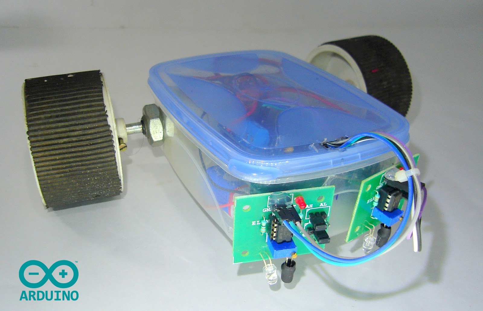
"A perfectly working line follower robot using arduino"
This is a simple tutorial to make a line follower robot using arduino. In this tutorial I am using the same robot platform of my previous tutorial "Make you first arduino robot". You can follow that tutorial to make the platform of this robot.
Watch the video here-
Here download all the files - Arduino codes + circuit diagram.

Parts needed
 |
| IR sensors |
 |
| Parts for making the chassis. |
 |
| Arduino |
 |
| Box |
Meterials-
- IR sensors - Buy here (Amzon.in, Amazon.com)
- Arduino uno - Buy here
- L293D motor shield - Buy here
- 2 x Gear motor - Buy here
- 2 x Wheel - Buy here
- Caster wheel - Buy here
- 3 x 9 volt battery
- 3 x battery clip - Buy here
- DC male jack - Buy here
- 8 x Female to female jumper wire - Buy here
- Plastic box (size - 14 cm x 10 cm)
Tools
- Screw driver
- Soldering iron
- Hot glue gun
- Driller
Step 1: Making changes from previous robot
 |
| Connecting the IR sensors |
If you are a beginner visit my previous tutorial for complete information and follow the steps 1 to 4.
After making the chassis. Connect the IR sensors as shown in the image. The position of IR LEDs and receivers are 0.5 cm from ground.
Step 2: Circuit diagram and sensor connection
 |
| Download and zoom in for clear view |
Wiring Instructions
- Connect the left sensor 'out' to the digital 'pin 8' of arduino
- Connect the right sensor 'out' to the digital 'pin 9' of arduino
- Connect the 'vcc' of both sensors to '5 volt' of arduino
- Connect the 'gnd' of both sensors to 'gnd' of arduino
Step 3: Code for the arduino
Install the 'AFmotor' library before compiling the program (Copy paste the AFmotor folder to to arduino libraries folder) Click here to download it.
 |
| Connect two header mail pins to pins 8 and 9 of motor shield. |
 |
| Take out the wires through the hole. |
 |
| Connect the wires to the sensors. |
 |
| Everything is completed. |
Step 3: Code for the arduino
Install the 'AFmotor' library before compiling the program (Copy paste the AFmotor folder to to arduino libraries folder) Click here to download it.
 /*
 Author: Muhammed Azhar
 visit - robotechmaker.com
 */
 #include "AFMotor.h";
 int IRleft = 8;   // the input of IR sensor right
 int IRright = 9;   // the input of IR sensor left
 //Objects
 AF_DCMotor motorRight(1, MOTOR12_64KHZ); // create motor #1, 64KHz pwm
 AF_DCMotor motorLeft(3, MOTOR12_64KHZ); // create motor #3, 64KHz pwm
 void setup() {
  Serial.begin(9600); // set up Serial library at 9600 bps
  pinMode(IRright, INPUT);   // sets the digital pin 9 as input
  pinMode(IRleft, INPUT);    // sets the digital pin 8 as input
   //Initalization messages
  Serial.println("ARDUINO LINE FOLLOWER");
  Serial.println(" Reday for working!");
   //turn off motors
  motorRight.setSpeed(0);
  motorLeft.setSpeed(0);
  motorRight.run(RELEASE);
  motorLeft.run(RELEASE);
 }
 void loop() {
  //for wall follower robot.
  motorRight.setSpeed(255); //set the speed of the motors, between 0-255
  motorLeft.setSpeed (255);
   if (digitalRead(IRright) == LOW)
   {
   Serial.println ("right Line is ditected!" );
   motorRight.setSpeed(255);
   motorLeft.setSpeed(80);
   motorRight.run(FORWARD);
   motorLeft.run(FORWARD);
   delay(500); // wait for a second
   }
   if (digitalRead(IRleft) == LOW)
   {
   Serial.println ("left Line is ditected!" );
   motorRight.setSpeed(80);
   motorLeft.setSpeed(255);
   motorRight.run(FORWARD);
   motorLeft.run(FORWARD);
   delay(500); // wait for a second
   }
   else {
   {
    Serial.println ("Placed in ground. No line ditected. Going forward");
    delay (15);
    motorRight.setSpeed(255);
    motorLeft.setSpeed(255);
    motorRight.run(FORWARD);
    motorLeft.run(FORWARD);
    }
   }}
"If you have any doubts or any suggestions please comment below"
Download the code


12 comments
Great! but could advice me the code, if we put that 2 sensor at analog sensor I/O ?
ReplyDeleteYes then also it will work. You only need to change the pin 8 and 9 to the analog pins you want.
Deleteint IRleft = 8;
int IRright = 9;
Please can you give me a code for four sensor
ReplyDeletePlease give code fast there is a competion in my school
ReplyDeleteAre you want to use the same type of two more sensors on either side of the present sensor? then I have written a code for you? Download it from here-
Delete***CLICK HERE***
Then connect you new sensors as -
new right sensor to arduino pin A1
new left sensor to arduino pin A0
replay this comment to know your robot is working or not.
also subscribe me on you-tube and like my FB page to stay updated. My new project tutorial videos and robots are coming soon in this summer holidays!
MY MOTORS ARE NOT ROTATING Y?
ReplyDeleteHey, before uploading my code pls check your motors and motor controller.
DeleteI checked everything from motors to ahelid and Arduino too IR sensors are also working !!! I don't know what is going wrong but I want to know that can I first insert wires and above that I actually put the sheild? That's the query
DeleteREPLY ASAP!!!!
ReplyDeletePls make an video or a project on line follower with obstacle avoiding using motor shield and arduino.
ReplyDeleteMy family every time say that I am wasting my time here at net, but I know I am getting familiarity everyday by reading thes good articles or reviews. gmail email login
ReplyDeleteyou can sent the AFmotor foler downlode link pleas fast i have project
ReplyDeleteClick on 'Notify me' to get replies of your comment.